|
|
|
Line Follower Robot
Features:
Atmega16L microcontroller based system
LMD18245 DMOS Full-Bridge Motor Driver
OPT101 Based Sensor
7 segment LED display for Status check

Port C is configured as Sensor I/P Port
PC0 - Forward Sensor
PC1 - Back Sensor
PC4 - Right Sensor
PC5 - Left Sensor
Port A is configured as O/P Port for LMD18245 Driver
PA0 - Direction (Right)
PA0 - Brake (Right)
PA0 - Direction (Left)
PA0 - Brake (Left)
Port D is configured as O/P Port for
PD0 - PD3 to IC7447 BCD to 7 segment decoder and driver
PD4 to Dot Point of 7 segment display to indicate line following or backtracking status
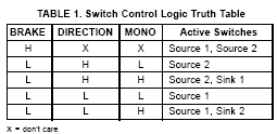
Truth Table of LMD18245 driver


M1 - M4 are connected to DIP switches for ease. It can be connected to microcontroller for speed control.
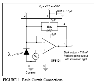
The OPT101 Photodiode

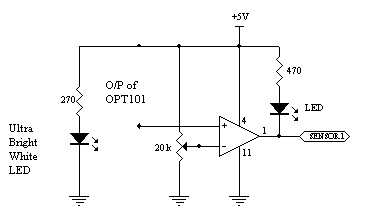
The LM324 Quad Comparator Circuit

The 20K Pot must be varied to adjust the sensors to the contrast of the line and the background. The O/P of this circuit is fed to the microcontroller.
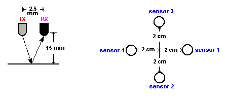
Position of Sensors

Datasheet References:
www.national.com : LMD18245, 74LS47
www.ti.com : OPT101
www.atmel.com : Atmega16L
The Atmega16L was programmed using At-prog All the details of the programmer dongle is available in the zip file.
Truth Table of Sensor I/P's and UC O/P's for driver (Fundamentals of the code)
Code of the linefollower (The code was written in AVR Studio 4. The zip file contains the .asm and .hex files, but the code is not perfect.)