|
|
|
Theory of Motors
Introduction:
The universal motor is characterized by its ability to operate, with substantially the same performance, on direct as well as alternating current of frequencies up to 60 Hz. It develops more horsepower per kg than other ac motors, principally because of its high speed. These motors are series-wound and have series characteristics on both alternating and direct current, except when governors or other means are used to control their speed. No-load speeds are high, sometimes well over 20,000 rpm; but the armatures are designed so that they will not be damaged at these speeds. Power ratings vary from 10 mhp to 1 hp, for continuous-rated motors, and even higher for intermittent-rated motors. They are usually designed for full-load operating speeds of 4000 to 16,000 rpm in the larger horsepower ratings, and up to 20,000 or more in the smaller power ratings. At the higher speeds, better universal characteristics (i.e., more nearly the same performance characteristics on both alternating and direct current) can be obtained, as well as more output per kg.
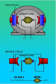 Universal
motors can operate on either AC or DC power. The rotor has coils that are
connected to an external circuit through a commutator on the shaft, as shown in
the schematic. Note that the field in the rotor will oppose the field in the
stator at any given moment, regardless of whether or not the polarity of the
supply current changes with time. This feature gives the universal motor its
unique characteristic. The price of versatility is efficiency; universal motors
are not as efficient as similarly-constructed AC and DC series motors.
Universal
motors can operate on either AC or DC power. The rotor has coils that are
connected to an external circuit through a commutator on the shaft, as shown in
the schematic. Note that the field in the rotor will oppose the field in the
stator at any given moment, regardless of whether or not the polarity of the
supply current changes with time. This feature gives the universal motor its
unique characteristic. The price of versatility is efficiency; universal motors
are not as efficient as similarly-constructed AC and DC series motors.
Principle of operation :
Operation on AC:
If alternating current is applied to a series motor, it will start and run. The current in the armature circuit, of course, reverses 100 times per second (for 50 Hz), but the field excitation and stator flux likewise reverse 100 times per second, and these reversals take place in time phase with the armature current. On alternating current, the torque varies instantaneously 100 times per second, but the torque developed is always in one direction. (It is, perhaps, superfluous to say that the motor operates in the same direction of rotation on alternating current that it does on direct current.) However, there are some effects present on ac operation that are not present on dc operation.
(1) Laminated-field construction: Because the stator flux alternates, it is necessary to use a laminated-field structure in order to reduce hysteresis and eddy-current losses.
(2) Reactance voltage: In a simple dc circuit, the current is limited by the resistance. In a simple ac circuit, the current is limited by the impedance and not solely by the ohmic resistance. The impedance is made up of two components, resistance and reactance. Reactance is present in an ac circuit whenever a magnetic circuit is set up by the current flowing in the electric circuit. Reactance is, therefore, present to a marked degree in the case of a universal motor. This reactance voltage, which is present during ac but not dc operation, absorbs some of the line voltage, reducing the voltage applied to the armature, so that the speed of the motor, for any given current, tends to be lower on alternating than on direct current. In other words, the effective voltage on the armature for any given current is less on ac than on dc operation.
(3) Saturation effect: In the Universal motor it is observed that the tendency of the reactance voltage is to make the speed lower on alternating than on direct current. There is another effect, which gives the opposite tendency. This effect is simply that a given root-mean square (rms) value of alternating current will produce less rms alternating flux than will a direct current of the same value because of saturation effects in the iron. At low currents and high speeds, the reactance voltage is relative1y unimportant, and this saturation effect usually causes the motor to operate at a higher no-load speed on alternating than on direct current. Likewise, under 25-Hz operation, the saturation effect is as pronounced as on 50 Hz, but the effect of the reactance voltage is appreciably less, in the ratio of 25:50. The net result is that the motor may sometimes operate at a higher speed on 25 Hz than it does on direct current.
(4) Commutation and brush life. The commutation on alternating current is substantially poorer than on direct current, and the brush life is likewise less. The principal reason for the poorer commutation on alternating current is because of the voltage induced in the short-circuited coils undergoing commutation by the transformer action of the alternating main field. No such transformer voltage exists when the motor is operated on direct current.
Operation on Direct Current:
(1) How torque is developed. A simple dc motor is represented schematically. Armature windings, together with commutator and brushes, are so arranged that the flow of current is in one direction in all the conductors on one side of the armature, and in the opposite direction in all the conductors on the opposite side of the armature. This condition is represented in the figure by the use of dots to indicate current flowing toward the observer, and by plus signs (representing the tail of an arrow) to indicate current flowing away from the observer, perpendicularly to the plane of the paper. The field winding sets up a magnetic field as shown in the figure. It is a simple fundamental law of motor action that, if current is passed through a conductor which is perpendicular to a magnetic field, a mechanical force will be exerted on the conductor, mutually perpendicular to both the conductor and the direction of the field. A rule for the direction of this force is given in the left-hand rule." Application of this rule to gives an upward force on all conductors to the left, and a downward force on all conductors to the right, so that a torque is developed in a clockwise direction.
(2) Counter emf: An understanding of the nature and role of counter electromotive force (emf) is absolutely essential to any comprehension of the way any type of dc motor works. Again let us refer to circuit diagram and let us assume that the armature is revolving in a clockwise direction, the same direction as the torque developed by the current. Because of rotation, the armature conductors are cutting the lines of force of the field, thus generating voltages in the armature conductors. Application of Fleming's right-hand rule shows that the direction of this induced voltage is away from the observer on the left, and toward the observer on the right; that is, the direction of the induced voltage is opposed to the direction of current flow. In sum then, in any DC motor, rotation of the armature induces a voltage in the armature circuit which opposes the flow of the current that causes the rotation. Because the direction of the voltage is counter to the applied voltage, it is called counter electromotive force.
(3) Basic performance equations: Performance characteristics may be succinctly expressed in the form of a few simple equations.
Let E = counter emf generated in the armature
Ia = armature current
N = rpm of the armature
Ra = total resistance in the armature circuit, including all
windings in the circuit, and brush-contact resistance
T = torque developed by the armature
V = voltage impressed on the armature circuit l/> = flux per pole
K1, K2, K3 = _roportionality constants
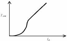
Now the torque is proportional to both flux and current, or
T = Kl/>Ia
Voltage induced is proportional to rate of cutting flux, that is, to the product of speed and flux, giving
E = K2Nl/>
The counter emf has to be the applied voltage less the IR drop, or
E = V - laRa
Solving the above equation for armature current gives
Ia = V - E
Ra
Speed can be determined from counter emf and flux by rewriting EQ. (12-2)
N = K3E
l/>
The ways these equations are interpreted and used for the various types will be discussed separately for each type.
(4) Armature reaction: Consider again the schematic representation of a dc motor in circuit diagram. In all the conductors to the left of the brushes the current is flowing out of the paper; in all the conductors to the right, the current is flowing into the paper. This is exactly the effect that would be produced by a coil of wire, wrapped around the armature, with its axis vertical. This coil tends to produce a magnetic field along the brush axis and perpendicular to the main-field axis. In general, that is exactly what the armature current does: it sets up, or tends to set up, a magnetic field which is displaced 90 electrical degrees from the main-field flux. Such an effect is known as armature reaction. Armature reaction has at least two harmful effects: it distorts the shape of the main field, usually weakening it in the process; it causes a voltage to be induced in the coils undergoing commutation, tending to produce sparking at the brushes. Commutation can be improved by shifting the brushes, if the motor construction permits, against rotation; this procedure is limited to motors that operate in only one direction of rotation. If the brush-holder positions are fixed, the effect of shifting the brushes can be obtained by shifting the coil connections to the commutator; this procedure is practicable only if the direction of rotation is known before the armature coils are connected to the commutator.
(5) Interpoles: The effects of armature reaction may be overcome by use of compensating windings, such as are used in some universal motors; in fractional horsepower sizes, it is done more commonly by the use of one or more interpoles. By selecting the proper number of interpole turns the field strength of the interpole is such as to cancel the armature-reaction magnetomotive force (mmf) plus counteract the inductive voltage of commutation, thus eliminating sparking at the brushes.
Interpole windings of motors must be connected so that any armature conductor passes under a main pole and then an interpole of the same polarity. Interpole windings of generators are connected so that any armature conductor passes under a main pole and then an interpole of the opposite polarity. If a motor is converted to a generator with the same direction of rotation, the interpole connections need not be changed, since the armature, and thus the interpole, current flows in the opposite direction.
How does the Series Motor Work?
The series motor is known as a varying-speed motor and has a very high no-load speed as can be seen in Torque v/s Speed Characteristics. The speed regulation is very much higher than for a shunt or compound motor. At standstill, the counter emf is zero, and the current is high-as is the field flux. so that the motor accelerates rapidly. As the motor accelerates, the counter emf increases with the speed. Now, in the case of a shunt motor, the counter emf increases directly in proportion to the speed because the flux remains constant. However in the case of a series motor, as the speed increases, the increased counter emf decreases the armature current, and this decreased armature current in turn decreases the field excitation. Therefore, as the motor accelerates, the weakening field makes it necessary that the armature rotate still faster to generate sufficient counter emf to limit the armature current. At light loads, the motor literally races; the armature races to develop enough counter emf to limit the armature current and as the armature current is limited, the field is weakened, thus tending to decrease the counter emf, so that the motor has to run still faster. Large dc motors will usually race to destruction if not loaded, but fractional horsepower dc series motors, as well as universal motors, generally are designed to withstand these high speeds.
Universal motors usually run at high speeds, 3,500 to 20,000 rpm. This results in a high power-to-weight and power-to-size ratio, making it desirable for hand-held tools, vacuum cleaners and sewing machines.
The Speed v/s Torque Characteristics shown below shows performance curves for a high-speed universal motor using different supply currents. Performance near rated load is similar for all supplies, starting torque is high, and speed regulation is poor. Note also that the speed gets very high at low loads. Theoretically, at zero load the speed becomes infinite, thus some universal motors (as well as AC and DC series motors) must employ speed controls.
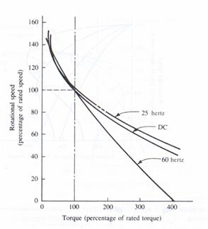
N v/s T characteristics.

An universal motor can be treated as DC series motor while testing for it’s performance on DC. A series wound DC motor has its armature and field connected in a series circuit. These type motors normally drive loads that require high torque and do not require precise speed regulation. Series DC motors are ideal for traction work where the load requires a high breakaway torque. Such uses include locomotives, hoists, cranes, automobile starters, or oil drilling rig applications.
Starting torque developed in series motors normally ranges between 300% and 375% of full load, but can be as high as 800% of full load torque.
An increase in load results in an increase in both armature and field current. As a result, torque increases by the square of a current increase.
Speed regulation in series motors is inherently less precise than in shunt motors. If motor load diminishes, current flowing in both the armature field circuits reduces as well. This results in a greater increase in speed than in shunt motors. Removal of mechanical load from series motors results in an indefinite speed increase which can destroy the motor or bearings. Small series motors usually have enough internal friction to prevent high-speed breakdown, but larger motors require external safety apparatus.
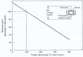
PERMANENT MAGNET DC MOTOR:
Permanent magnet motors are well fit for use where response time is a factor. Their speed characteristics are similar to those of shunt wound motors. Built with a conventional armature, they use permanent magnets rather than windings in the field section. DC power is supplied only to the armature. Since the field is constant at all times, the performance curve is linear, and current draw varies linearly with torque.
Permanent magnet motors are not expensive to operate since they require no field supply. The magnets, however, lose their magnetic properties over time, and this effects less than rated torque production. Some motors have windings built into the field magnets that re-magnetize the cores and prevent this from happening.
Automobiles have installed DC permanent magnet motors that control power seats, windows, and windshield wipers. DC permanent magnet motors produce high torque at low speed, and are self-braking upon disconnection of electrical power. Permanent magnet motors cannot endure continuous operation because they overheat rapidly, destroying the permanent magnets.
Comparison of Methods of loading for Testing of Motors
|
Parameter |
Dynamometer Loading |
Pulley Method |
Hysterisis Braking |
|
Method |
Motor to be tested is coupled with a separately excited dynamometer. As the Vf is increased, the motor gets loaded |
The shaft of motor is manually loaded with weights, using belt-pulley arrangement. As we increase the weights, the load increases |
A ferro-magnetic disc which is under the influence of a magnetic field is mounted on the motor shaft. As the strength of the field increases, the motor gets loaded |
|
Controlling parameter |
Field voltage of dynamometer |
Weights on the pan |
Strength of the external field |
|
Feasibility |
Variation of voltage is the easiest and smoothest |
Variation of load in steps, can be done only manually |
Variation of voltage is the easiest and smoothest |
|
Major Losses |
Coupling loss |
Friction between belt and shaft |
Leakage flux |
|
Application |
Suitable for all types of motors |
Used for testing low speed, FHP motors |
Suitable for large motors |
|
Efficiency of method |
Accurate |
Not accurate |
Accurate but not suitable |